API Gateway Platform  ·  View 06 of 21  ·  Structure

Layered Architecture

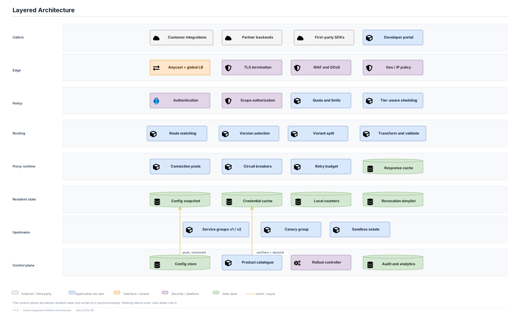
Eight layers, and the one arrow that defines the platform points downward.

Editable source SVG draw.io All views
Callers Customer integrations Partner backends First-party SDKs Developer portal Edge Anycast + global LB TLS termination WAF and DDoS Geo / IP policy Policy Authentication Scope authorisation Quota and limits Tier-aware shedding Routing Route matching Version selection Variant split Transform and validate Proxy runtime Connection pools Circuit breakers Retry budget Response cache Resident state Config snapshot Credential cache Local counters Revocation denylist Upstreams Service groups v1 / v2 Canary group Sandbox estate Control plane Config store Product catalogue Rollout controller Audit and analytics push, versioned verifiers + denylist Layered Architecture External / third party Application we own Interface / broker Security / platform Data store event / async The control plane sits below resident state and writes to it asynchronously. Nothing above ever calls down into it. v 1.0 · owner Integration Platform Architecture · date 2026-09

Decisions

  • Resident state sits between the proxy runtime and the upstreams, because it is read by the runtime and is never a network call.
  • The control plane is drawn at the bottom and writes upward asynchronously. Nothing above it ever calls down into it — this is ADR-01 rendered as a layer diagram.
  • Policy is a layer above routing: a request is refused before a route is selected, so a rejected caller never learns the shape of the internal estate.

Assumptions

  • The credential cache holds verifiers with a 5-minute TTL; the denylist is pushed with a 30 s propagation SLO (assumptions).
  • Local counters and the shared counter store are separate layers of the same limit decision, per ADR-05.

Omitted

  • The developer portal appears in the caller layer because it is, architecturally, just another authenticated client of the control plane.